top of page
Como cambiar una sonda RS-41 a 70 cm y demas parametros...
CX4AE FERNANDO MANACORDA SCHMITD - CX1AAO JOSE OLIVERA ARELLANO - LW8EUA DIEGO MEZZINI
AC6RB GEORGE MIGLIARINI
Como logré capturar algunas radiosondas meteorológicas RS-41 de Vaisala, decidí buscarles alguna utilidad. Dado que la frecuencia a la que transmiten estas radiosondas está protegida y asignada a los meteorólogos, es necesario encontrar una manera de cambiar la frecuencia a la banda de aficionados o ISM. La radiosonda utiliza un circuito integrado de radio de tipo Si4032, por lo que este trabajo es solo una cuestión de programación. Desafortunadamente, es una práctica habitual que el programa en estos dispositivos esté protegido para que solo se pueda caminar de una manera: se debe volver a escribir todo el programa. Durante la búsqueda en la red me encontré con un programa publicado por un radioaficionado polaco, SQ5RWU. Programé una radiosonda con este software y comencé a probarla. El programa funcionaba, pero era incómodo que cada vez que quería cambiar algunos parámetros, era necesario cambiar el código fuente y compilarlo y luego volver a escribir el nuevo programa en el procesador. Este es un proceso que requiere mucho tiempo y, por otro lado, a la memoria flash no le gusta la reescritura frecuente. Como todo el programa era simple y las posibilidades que me brindaba no eran suficientes, decidí reescribir todo el programa. El resultado final de este desarrollo es este programa. Es bastante grande, apenas cabe en el flash, pero la ventaja es que no tiene que reescribir constantemente la radiosonda. El programa debe colocarse una vez en él, luego los parámetros se pueden cambiar en cualquier momento a través de la línea serial en el puerto del conector rs41. Antes de la primera programación, la memoria flash debe eliminarse por completo con el comando "Borrado completo del chip" para que se liberen las partes de la memoria originalmente protegidas. De lo contrario, el programa no guardará nuestros propios parámetros debido a la falta de espacio.


Descripción:
La radiosonda se puede encender con el botón en la esquina inferior derecha. Si el voltaje de la batería es suficiente (la radiosonda puede funcionar con dos baterías de NiMH), el LED verde en la parte inferior izquierdaesquina de la PCB comenzará a parpadear. Si la radiosonda tiene una buena vista de los satélites GPS, el LED verde se encenderá permanentemente después de encontrar su posición. El LED rojo cercano se enciende cuando el transmisor está funcionando. Los sensores originales no se utilizan, por lo que hay que retirarlos. Si el parámetro BOTÓN está configurado en ENCENDIDO, la radiosonda se puede apagar manteniendo presionado el botón. Presione el botón hasta que el LED verde comience a parpadear rápidamente. Después de soltar el botón, la radiosonda se apaga. Si el BOTÓN está APAGADO, la radiosonda solo se puede apagar retirando las baterías del soporte de baterías.
La radiosonda puede operar en modo RTTY, APRS y CW. Estos modos se pueden activar o desactivar individualmente. El texto RTTY es compatible con las recomendaciones UKHAS. El paquete APRS puede descifrarse y codificarse según la variable Mic-E. Sonda que transmite datos APRS solo si las coordenadas son válidas. Cada parámetro se puede cambiar enviando un comando y sus parámetros por el puerto serie. Para hacer esto, la radiosonda y la computadora deben estar conectadas a través de un convertidor COM-TTL o USB-TTL. ¡Tenga en cuenta que el conector de la radiosonda en el puerto UART es de 3,3 V! Puede usar cualquier programa de terminal en su computadora. La velocidad es de 9600 baudios, 8 bits de datos y 1 bit de parada sin control de paridad y hw (9600 8-N-1). Como cualquier otro parámetro, esto también se puede cambiar. Las velocidades posibles son de 300 a 115200 baudios.La comunicación es interactiva. Todos los comandos emitidos serán respondidos. Si el procesador entendió y ejecutó el comando, entonces la respuesta será OK. De lo contrario, recibiremos un mensaje de error que le indicará dónde cometimos un error. Después de encender la radiosonda, necesitamos ver este texto de bienvenida en la pantalla, si la radiosonda y la computadora están correctamente conectados :
STM32 CW, RTTY & APRS tracker v. 2.5 by OM3BC...
cmd>
If you need help, you can use the HELP or the ? commands. After this command we get the following text:
cmd>help
Allowed commands (not case sensitive):
BUTTON on/off - use button to turn off
LEDS on/off - use LEDs
POWER n - rf power n = 0 to 7 (7 is max.)
HOLDOFF n - n = time between two rtty messages in seconds
SERCOM n - speed of serial communication port (n = 300 to 115200)
RTTY on/off - send rtty message
RTTYFRQ n.n - n.n = rtty and cwid frequency in MHz
RTTYCALL string - rtty callsign (up to 15 characters)
BAUD n - n = rtty baudrate (max. 300)
DBITS n - n = rtty databits (7 or 8)
SBITS n - n = rtty stop bits (1 or 2)
SHIFT n - n = 1,2,3,4 or 270,540,810,1080 Hz
TEMP (or TEMPERATURE) on/off - send temperature in rtty messages
ALT (or ALTITUDE) on/off - send altitude in rtty messages
SPEED on/off - send speed in rtty messages
COURSE on/off - send course in rtty messages
UBAT on/off - send battery voltage in rtty messages
RTTY_WWL n - n = characters of wwlocator (only even numbers) in rtty messages
RTTY_TIME on/off - send time in rtty messages
SAT (or SATELLITES) on/off - send heard satellites in rtty messages
APRS on/off - send aprs messages
APRSFRQ n.n - n.n = aprs frequency in MHz
APRSCALL string - aprs callsign (up to 6 characters)
SSID n - aprs ssid n = 1 to 15
APRS_ALT on/off - send altitude in aprs ttext
SYMBOL string - symbol from aprs symbol table (2 characters)
RELAY string - aprs relays (WIDE1-1,WIDE2-1)
APRS_EVERY n - time between aprs messages is n x holdoff
TAIL_EVERY n - time between tail text is n x aprs time, 0 = no tail text
TTEXT string - tail text (up to 100 characters)
APRS_UBAT on/off - send battery voltage in aprs ttext
APRS_TEMP on/off - send radio chip temperature in aprs ttext
CWID on/off - send cwid messages
CWIDMESS string - cw message (up to 25 characters)
CWID_ALT on/off - send altitude via cw
CWID_UBAT on/off - send battery voltage via cw
CWID_WWL n - n = characters of wwlocator (only even numbers) in cw messages
CWID_EVERY n - time between cw messages is n x holdoff
CW_SPEED n n = cw speed in wpm
DISP - show parameters
DEF - set default values
SAVE - save parameters to flash
cmd>
Available commands:
BUTTON - this parameter specifies whether the push button can be used to turn off the radiosonde or not.
LEDS - you can save energy when you do not use LEDs. Nobody sees them anyway when the radiosonde is flying. After switching on, the LEDs always work, but when set to OFF, they automatically turn off after 10 minutes of operation.
POWER - output power setting 0 = smallest, 7 = maximum power (approx. 40 mW).
APRSFRQ - APRS frequency (recommended frequency is 432,500 MHz)
RTTYFRQ - RTTY frequency. This frequency is also valid for CW identification.
APRSCALL - APRS call sign.
RTTYCALL - RTTY call sign.
CWIDMESS - the text of the CW identification. If you write a > at the beginning of the text, the broadcast will begin with a "attention" (-.-.-) sign, which facilitates machine decoding (MixWin, Dl-FlDigi, etc.).
RTTY - RTTY Text On / Off.
HOLDOFF - the time between the two RTTY broadcasts.
BAUD - RTTY transmission speed in baud (max. 300).
DBITS - number of data bits. Possible values are 7 or 8.
SBITS - number of stop bits. Possible values are 1 or 2.
SHIFT frequencies. Possible values: 1-270, 2-540, 3-810, 4-1080 Hz
TEMP - to transmit the temperature in the RTTY text. (The value is the temperature of the radio chip, not the environment.)
ALT - enable altitude transmission.
SPEED - enable speed transmission.
COURSE - enable motion direction transmission.
UBAT - enable battery voltage transmission.
SAT - the number of GPS satellites heard.
APRS - Enable APRS transmission.
SSID - the caller ID of the APRS. Possible values from 0 to 15.
RTTY_TIME - send time in RTTY messages.
SYMBOL - two characters that determine how the radiosonde appears on the www,aprs.fi website. Icon from the symbol table
RELAY - aprs relays (WIDE1-1,Wide2-1).
APRS_EVERY - APRS packages are not required to be given too often. This parameter specifies the time between the two packets.
TAIL_EVERY - frequency of transmission of the attached information text (comment field).
TTEXT - the attached information text (comment).
APRS_UBAT - Send battery voltage in aprs text.
APRS_ALT - Send altitude in aprs ttext.
APRS_TEMP - Send radiochip temperature in aprs ttext.
CWID_WWL or RTTY_WWL- Send n charakters of WW Locator. n = 0 for no WW Locator
CWID - Enable CW Authentication.
CWID_EVERY - Frequency of CW identification.
CW_SPEED - the CW identification speed in WPM.
DISP - shows the set parameters.
SERCOM - speed of serial communication port (n = 300 to 115200).
DEF - set parameters to default values.
SAVE - stores the set parameters.
One possible setting:
cmd>disp
Current parameters:
BUTTON ON
LEDS OFF
POWER approx. 100 mW
UART 9600 8-N-1
HOLDOFF 10 s
RTTY ON
RTTY and CWID FREQUENCY: 434.500 MHz
RTTY CALLSIGN: OM3BC/AM
RTTY BAUDRATE: 100 Bd
RTTY SHIFT: 540 Hz
RTTY DATA BITS: 7
RTTY STOP BITS: 2
RTTY TEMPERATURE: OFF
RTTY ALTITUDE: ON
RTTY SPEED: OFF
RTTY COURSE: OFF
RTTY BATTERY VOLTAGE: ON
RTTY SATELLITES: ON
RTTY WWL: OFF
RTTY TIME: ON
APRS ON
APRS FREQUENCY: 432.500 MHz
APRS CALLSIGN: OM3BC-11
APRS RELAY: WIDE1-1
APRS SYMBOL: /O
APRS EVERY: 1
APRS ALT: ON
APRS TAIL TEXT EVERY: 1
APRS TAIL TEXT: Modified RS-41 balloon tracker
APRS UBAT: ON
APRS TEMP: ON
CWID ON
CWID MESSAGE: TEST DE OM3BC/AM
CWID speed: 60 WPM
CWID EVERY: 5
CWID WWL: 6 characters
CWID UBAT: OFF
CWID ALT: OFF
cmd>
Closing remarks:
The original source can be found here.
Hex file can be found here.
For programming, I use the ST-LINK V2 programmer, which can be obtained from aliexpress, for example.
HG8LXL, Laci's report on the balloon, he has launched.
Wiring:
RS-41 connector:
| ----------- |
| 2 4 6 8 10 |
| 1 3 5 7 9 |
| ------ ---- |
1 - GND
2 - Uart3 Rx
3 - Uart3 Tx
4 - PB1 * (10k + cap + 10k)
5 - Vcc (Boost out)
6 - VBAT
7 - RST
8 - SCL
9 - SDI
10- GND
The Programer cable connections:
RS41 ----- ST-LINK
===================
Pin 1 ----- GND - Cable Negro
Pin 5 ----- 5.0V - Cable Rojo
Pin 8 ----- SWCLK - Cable Azul
Pin 9 ----- SWDIO - Cable Naranja
USB - TTL converter:
RS41 ------ USB-TTL
===================
Pin 1 ----- GND - Cable Negro
Pin 2 ----- TxD - Cable Blanco
Pin 3 ----- RxD - Cable Amarillo
Software necesario
STM32CubeProgrammer software for all STM32
How To Flash a target using STM32 Cube Programmer
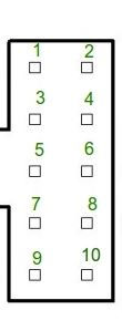
RS-41 Sonda Conector
bottom of page